
[et_pb_section bb_built="1"][et_pb_row][et_pb_column type="4_4"][et_pb_text _builder_version="3.0.101" background_layout="light"]
What happened recently was that from one day to the next, I had to throw two seemingly proper cables in the trash because they simply burned out. Due to the loss of power supply to the graphics card, fortunately nothing else happened besides the disconnected graphics card, in the middle of the night of course.
What's certain is that when building mining rigs, you absolutely must pay attention to only using the best quality power supplies and cables for the wiring after assembly. They carry much greater risk no-name or low-quality power supplies and their included cabling solutions than one might initially think. We can even cause a complete house fire if we don't pay proper attention to this.
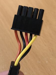
A healthy power cable of a Zalman ZM770-XT power supply
The most important thing! Don't order power supplies from unknown manufacturers from unreliable sources. By unreliable sources, understand China too, because in many cases their testing phase ends at printing the label. This is still no guarantee that everything will be fine with what we ordered.
The point isn't just that it catches fire or cables melt, but our components worth tens or hundreds of thousands of forints can also be instantly consigned to the hardware cemetery forever, because a pleasant voltage surge doesn't exactly have a beneficial effect on them either.
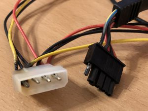
The images in this post were taken of the connectors that couldn't handle the strain and gave up. The power supply to be exact is a Zalman ZM-770XT (http://www.zalman.co.kr/contents/products/view.html?no=259) power supply which has been with me precisely since May 2009, so it's slowly approaching 10 years old but fortunately it's still going strong. The PSU is an 80Plus Bronze rated unit but in this case it's not that relevant.
What's much more interesting is the following calculation: under exactly what conditions did the complete melting of the outer casing of one cable's PSU-side connector occur, as well as the melting of the Molex cable.
- Zalman ZM-770XT – 4 12V rails, each rated for 20A:
- 100 Watts: Motherboard + Intel i7-920 – The processor has a 130W TDP, the motherboard is a Gigabyte X58 Extreme. The processor is too old to be usable for mining, so it doesn't load the PSU, but let's count 100W for the motherboard + processor combo.
- 75+75=150 Watts: Two ASUS GTX1050Ti graphics cards powered through PCIe risers, with a combined power draw of approximately 12.5 Amps, so the separate 12V rails can easily handle it on one cable with 3 SATA power connectors, of which only the two cards are connected.
- 120+120=240 Watts: Two ASUS GTX1060 graphics cards also powered through PCIe risers from one cable with 3 SATA connectors on a separate 12V rail. But I don't think this is that significant since they also require a 6-pin PCIe power connector, and since the PSU has exactly 2 6+2 pin PCIe power cables, they're powered through those.
- Total system consumption: 490 Watts which the 770W power supply handles without significant heat or fan noise.
So then why did the shared connector cable end of the two 1060 cards burn up, and also the Molex connector of the cable for the 1 GTX1060 (with separate PCIe 6-pin power) that was disconnected for testing, along with the GTX1050Ti?
- To be very precise:
- GTX1050Ti: 75W TDP, so the two cards are 150W which is 12.5 Amps.
- GTX1060: 120W TDP, so the two cards are 240W which is exactly 20 Amps.
- BUT! Exactly 20 Amps would be justified if it received this amount of current through the PCIe riser via the PCIe bus and didn't require a separate PCIe 6-pin connector. (Let's not get into the fact that it can't receive this much through the PCIe bus, that's not the point...)
- So where's the catch? What's the problem here? The cables have an 18AWG rating, about which in-depth info can be found on Wikipedia (https://en.wikipedia.org/wiki/American_wire_gauge) for those who are very interested.
- AWG18:
- This means precisely a 1.024mm (0.8230mm²) cable diameter. But for simpler calculation, let's stick with the 1mm diameter.
- Just for fun... In most households, the electrical wiring in the walls is typically done with 1.5mm cables. Thinner wires are enough for chandeliers and switches, and extension cords typically have 1mm wire thickness — like most orange extension cords. But this is really just for fun, it has nothing to do with computer PSUs and cables...
- There is a calculator, (there are several, but I chose this one) where it shows us what cable thickness we would need for DC cables after entering the voltage, amperage, and length.
- Here I entered that it's a 12V system where I want to supply the 75+75=150W of the two GTX1050Ti cards on a 40cm cable, which in reality isn't longer, and even at 50cm the value doesn't change, which is 5mm² (17A max) and this corresponds to an AWG14 cable.
- AWG14 – What we would actually need!
- This cable, unlike the AWG18, doesn't have a ~1mm wire thickness but rather 2.5mm.
- The AWG18 cable can handle a maximum of 6-8 Amps without any particular issues and without even starting to heat up significantly.
- Powering the two GTX1050Ti cards with AWG18 cable is not appropriate, as the cable may overheat and melt, potentially melting the connector in the manner shown in the pictures.
- A Zalman ZM-770XT none of the cables that came with the PSU meet this requirement. So even though we have 4 separate rails on the PSU side, each capable of drawing 20 Amps, our cable can't even handle half of that.
- But then how can 1 GTX1050Ti at 75W (6.25 Amps) and 1 GTX1060 with its own PCIe 6-pin power burn up a cable rated for a mandatory 6-8 Amps, along with its connector?
- Let's assume that the GTX1060 draws most of its power through its PCIe connector, not through the PCIe bus, so it essentially doesn't significantly load the cable — at least not enough to cause problems. But then how?
- Because these connectors aren't designed for this level of current draw. These connectors, even if the cable could handle it, give up and melt the cable where the current flow is highest.
- Solution?
- Since I don't have such special connectors, I can't replace the cabling. But I still have plenty of complete cables with 3 SATA connectors that came with the PSU, so:
- The 2 GTX1060 cards are on one power cable with 2 SATA connectors powering the two PCIe risers. The two separate PCIe connectors ensure the necessary power supply for them.
- The 2 GTX1050Ti cards are on two separate cables with 3 SATA connectors each, so they receive their ~6.25 Amp demand alongside their 75W consumption on separate cables.
Currently, with this solution the cables don't heat up and everything has been running fine. I'm not touching the cables for now, but I'd like to precisely measure with a multimeter after a future rebuild how many Amps flow through each cable, focusing particularly on the PCIe riser + PCIe powered cards.

So what's the lesson from all this? That you don't just need to pay attention to how many Watts your PSU can deliver, but also what load ratings the included cables can handle. So it's not as simple as most people would think, which is why it's definitely worth asking an expert or not tempting fate. If our PSU provides us with 4 separate cable bundles with 6+2 or 4+4 pin PCIe power connectorsthen we definitely shouldn't try to expand this with DIY or other doubler solutions. Let's be satisfied with the 4 PCIe cable bundles and run 4 PCIe-powered cards from the given PSU.
Or buy a larger PSU with more connectors, or set up a secondary PSU. I'll write about the latter soon... But definitely use common sense! Nobody wants to burn down their machine, their RIG stand, or set their room on fire. Even though it's 12V — just think of cars catching fire on the roadside — let's not forget that there's "only" 12 Volts there too…
[/et_pb_text][et_pb_gallery _builder_version=”3.0.101″ gallery_orderby=”rand” posts_number=”2″ show_title_and_caption=”on” show_pagination=”on” gallery_ids=”276,270,275,274,273,272,271″ fullwidth=”on” orientation=”landscape” zoom_icon_color=”#dd3333″ hover_overlay_color=”rgba(255,255,255,0.9)” background_layout=”light” pagination_font_size_tablet=”51″ pagination_line_height_tablet=”2″ saved_tabs=”all” /][/et_pb_column][/et_pb_row][/et_pb_section]


Comments
Share your view: questions, corrections, and counterpoints are welcome. Comments are for constructive, useful discussion.